Our other sites:

What are the parts of a standard metal hand plane?

What are the parts of a standard metal hand plane?

Most metal hand planes follow a design, or pattern, developed by American Leonard Bailey and further refined by Stanley Works, again in the U.S.

Lever Cap

The design includes a metal clamp – the lever cap – that holds the iron or blade assembly in place. The lever cap is secured with a screw and a cam.


The cam is a projection beneath a lever that, when moved to its locked position, presses the lever cap against the screw and holds the iron and a chip breaker in place underneath.

Chip Breaker

The chip breaker, fitted on top of the iron and beneath the lever cap, breaks the shaving, or chip, that results from planing action on the wood.


It’s this breaking of the chip that gives it its distinctive, curly shape.

Iron

The irons of many metal planes have a large keyhole slot cut out of them to allow securing screws and the end of a blade depth adjustment lever to pass through it. 


The iron is usually bedded – secured in the plane – at an angle of 45 degrees to the sole, with the bevel of the cutting edge facing down towards the workpiece.

Iron Adjustment

There is a wheel and a lever for, respectively, adjusting the depth of the blade and the angle of the cutting edge in relation to the sole, known as the lateral angle.


The cutting edge should be perfectly parallel to the sole – if it’s skewed, moving the lateral adjustment lever to the left or the right will correct it.

Tote

The main (rear) handle, often referred to as the tote, is shaped to fit the user’s dominant hand comfortably.

Knob

The knob, or front handle, is gripped by the woodworker’s non-dominant hand during planing.

Frog

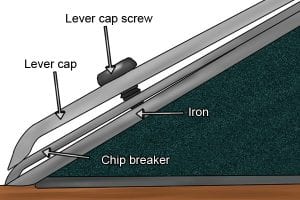
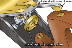
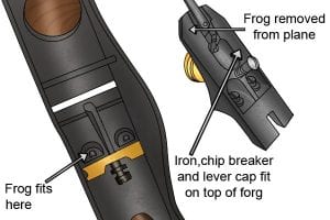
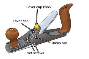
The iron, chip breaker, lever cap and iron adjustment mechanisms are mounted on an iron wedge known as the ‘frog’.


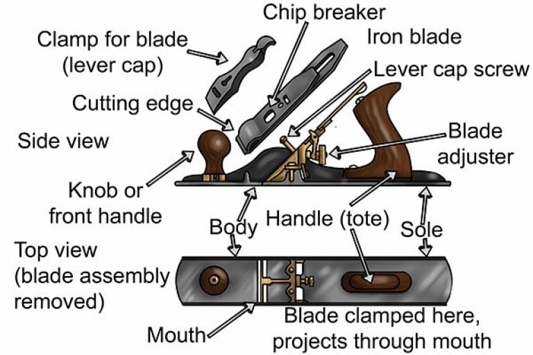
The frog is adjustable backwards and forwards to change the gap between the blade and the front of the mouth – the opening in the sole of the plane through which the blade projects. A wide gap is needed for deep cutting and a narrow one for fine cutting. 


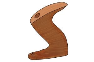
There are different theories about how it came to be known as the frog. One is that it actually resembles a frog, which is roughly wedge-shaped when sitting; another is that it is positioned just behind the ‘throat’ – the area through which the shavings curl upwards – alluding to having “a frog in one’s throat”.

Sole

The sole is the base of the plane, which slides along the workpiece during planing. It needs to be perfectly flat to give “true” results – edges that are perfectly flat and square, or perpendicular, with adjoining edges and faces.


The soles of some planes are corrugated – they have a series of grooves along their full length – to reduce friction between the sole and wood being planed. This is particularly useful on “sticky” woods, such as pitch pine, which contains lots of resin.

Low Angle Bevel-Up Planes

Apart from the standard Stanley / Bailey design, there are also low-angle planes which have their irons bedded at a lower angle – as little as 12 degrees – with the bevel of the iron’s cutting edge facing up, away from the workpiece, rather than down. 


Confusingly perhaps, this design was also originated by Stanley!

Simpler Designs

However, some metal planes follow a simpler design, like the scrub plane which is used for the fast removal of excess wood. The iron is held by a lever cap with a threaded knob, levered against a clamp bar, and there is no chip breaker. 


Blade depth adjustment is manual after slackening the lever cap knob, and lateral blade adjustment is via ‘set screws’ either side of the plane’s body.

Wonkee Donkee Tools
Logo