


What are the parts of a pointing and grouting gun?
What are the parts of a pointing and grouting gun? |
||||
 |
||||
Pointing and grouting gun applicator frame |
||||
 |
The applicator frame is usually made from steel and consists of the trigger, trigger release lever, drive parts, plunger and plunger arm. The chief function of the applicator frame is to hold the tube of mortar material in place so that the plunger and plunger arm can be inserted into it. | |||
Pointing and grouting gun plunger and plunger arm |
||||
 |
The plunger and plunger arm run through the centre of the applicator frame and are retracted by holding down the trigger release lever and pulling back the plunger arm.
Please noteA common feature on pointing and grouting guns is the curved end on the plunger arm, known as a “ladder hook”. This allows you to hook the gun onto a work belt or ladder so that you can free up your hands at a moment’s notice. |
|||
 |
The plunger also functions to drive the mortar material forward in the tube and dispense it through the nozzle. | |||
Pointing and grouting gun tube |
||||
 |
The tube is the part that holds your filler or mortar material. Tubes can be easily removed, refilled and reattached to the applicator frame. Because they are easily detachable, you can refill quicker too! | |||
Pointing and grouting gun nozzle |
||||
 |
The nozzle of a pointing and grouting gun directs your mortar material with a shaped point. There are several types of nozzle, each with a particular use.
Their uses are described in greater detail on the page: What pointing and grouting nozzle shapes are available? |
|||
Pointing and grouting gun trigger mechanism and drive parts |
||||
 |
The trigger mechanism is made up of the trigger lever, trigger release lever, drive parts and plunger arm. The trigger mechanism’s function is to drive the plunger arm forward until the plunger meets the mortar material and forces it through the nozzle. | |||
 |
All pointing and grouting guns are fitted with a ‘high-thrust’ trigger action. This allows the user to apply greater pressure with minimal effort.
A common trigger ratio is 12:1. This means that for every 1lb of pressure you apply to the trigger, 12lbs of pressure is applied to the material. This is known as the “mechanical advantage”. Any mechanism that employs gears or levers to decrease the effort needed to move a particular load employs a mechanical advantage. |
|||
 |
When the trigger is squeezed the drive parts push the plunger arm forward. | |||
 |
The plunger attached to the end of the arm then forces the material / filler out of the nozzle. | |||
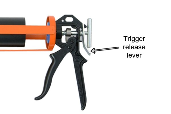 |
The trigger release lever prevents pressure applied to the material from pushing the plunger backwards. It allows movement of the plunger in the forward direction only. Pushing on the lever allows withdrawal of the plunger so that the tube can be refilled. | |||
