


How are hand drills and braces manufactured?
How are hand drills and braces manufactured? |
||||
|
|
||||
 |
Different manufacturing methods are used to make the different parts of the hand drill and brace.
Casting of one form or another is used to make the frame and drive wheel, while wooden handles are produced by a lathe or milling machine. |
|||
Hand drills |
||||
 |
Drive wheelsHand drill drive wheels are made using casting. Steel drive wheels will require additional machining of the drive wheel teeth to achieve the required accuracy following the casting process, whereas aluminium alloy drive wheels can be produced using more accurate die-casting, so the teeth will often not require any additional machining. |
|||
 |
What is die-casting?Die casting is a manufacturing process that uses a mould which can be reused, this is normally made of steel. |
|||
 |
The parts used in a die casting process are;
|
|||
 |
Molten metal from within the chamber is forced into the mould cavity between the two die halves, under high pressure by the plunger. This pressure is maintained whilst the metal solidifies. | |||
 |
Once the molten metal has solidified, the movable die half separates from the fixed die half and the ejector pins release the finished part from the mould. | |||
 |
FramesThe manufacturing method used for hand drill frames depends on what material the frame is made of. Aluminium frames are die-cast in the same way as aluminium drive wheels, whereas steel or iron frames have to be sand cast and then undergo additional machining. |
|||
 |
What is sand casting and why is it used?Sand casting is a casting process that uses a mould made of sand. Unlike many other casting processes, sand casting can be used with metals that have a very high melting point such as steel. |
|||
 |
The parts of a sand casting mould are:
|
|||
 |
The molten metal is poured into the pouring cup of the mould. From here it travels down the downsprue, along the runner and fills the mould cavity and riser. A core is sometimes used to form internal shapes within the casting. | |||
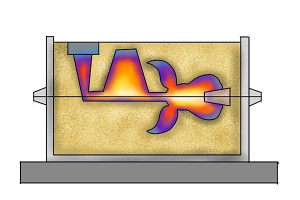 |
Once filled with molten metal, the casting is left to solidify and cool. As the molten metal solidifies, it will shrink in volume. A riser is used to maintain the accuracy of the casting, as the metal in the mould cavity shrinks, it is topped up by the molten metal in the riser, ensuring the mould cavity is always full. | |||
 |
Once the metal has cooled, the two halves of the mould (the cope and drag) are separated and the sand breaks away from the metal part inside. | |||
 |
Sand casting is not as accurate as die-casting so the cast part will require additional machining to produce smooth surface finishes or add threads for handles or other parts to screw onto. | |||
Handles and heads |
||||
 |
Plastic and TPR (rubber) handlesThe plastic and rubber handles and heads of hand drills and braces are manufactured using injection moulding. Injection moulding is similar to die-casting but differs in the way the material is heated and injected into the die halves. |
|||
 |
Parts of an injection moulding machine:
|
|||
 |
The feed hopper is filled with plastic resin beads that enter the barrel and are driven forward by the reciprocating screw.
As the plastic resin is pushed forward, friction between the resin beads and the barrel start to melt the plastic. This is aided by the heaters surrounding the barrel. |
|||
 |
The temperature of the molten plastic within the barrel can range from 160°C-320°C | |||
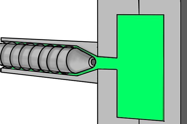 |
Once enough molten plastic has been built up in front of the reciprocating screw, the screw is pushed forward, closing the non-return valve and forcing the molten plastic through the nozzle and into the mould. | |||
 |
The molten plastic then solidifies within the mould. The movable plate is then drawn back, separating the two halves of the mould and ejecting the finished part. | |||
 |
Wooden handlesWooden handles are made using milling machines and lathes. These days this process is automated and often CNC (computer numerically controlled), which helps speed up production and reduces labour costs in the manufacturing process. |
|||
 |
A lathe holds the wooden workpiece between the headstock and tailstock. | |||
 |
The workpiece is then spun and a cutting tool is moved in, out and along the workpiece. As the cutting tool is moved, it removes wood from the workpiece until the desired shape is achieved. | |||
